

Failure Analysis
The following failure analysis descriptions are written as a general cause of each listed symptom but DFC would like to remind our customers that an engine can fail as a result of not just any one of these descriptions but sometimes multiple causes. When analyzing an engine failure all clearances, condition of components, operation and service of the vehicle must be taken into consideration. DFC has accumulated knowledge and intimate details of each of the engines we remanufacture acquired by years of research and development with our processes. We apply our knowledge of what can cause a failure to find a way to prevent one in every engine we supply.
While DFC does not void your warranty for running aftermarket engine enhancements like almost all other manufacturers, we also like to remind our customers that even aftermarket programmers have set limits of use. This is to say that when towing you should be on the Tow tune and when driving on the street you should not be on a Race tune. Our street and tow/haul series of engines are built to handle additional power adders such as a programmer/tuner, cold air intake, exhaust, mild injector and turbo upgrade’s but still have design limits that when exceeded, are not a parts, materials or workmanship failure and as such cannot be covered under the terms of our warranty.
Understanding the strengths and weaknesses of each engine is the only way to truly supply a superior product which we continually strive to achieve. While there are many more potential causes for failure we have only listed the most common we encounter.
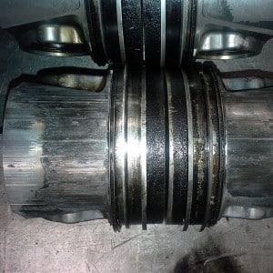
MELTED PISTON
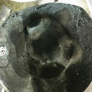
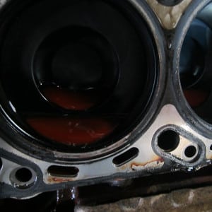
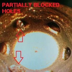
Crown damage by erosion is described as having the piston crown eroded, due to mechanical overloads and thermal disintegration. This is generally caused from excessive and/or premature fuel injection from the anticipated injection point with a lack of oxygen for the fuel available. When this occurs individual fuel droplets can be distributed throughout the entire combustion chamber and end up further outside on the piston crown on its downward stroke. There they glow away under a shortage of oxygen, generating a lot of heat in the process eventually leading to erosion. Ingestion of additional fuel sources (oil, fuel, etc.) through the intake can also cause an unregulated injection point in the cylinder causing piston erosion as does not receive enough air volume to offset the amount of fuel being burned.
As this type of failure is generally caused from excessive/premature fuel injection, incorrect spraying and leaking injector nozzles injectors MUST be removed for testing or replaced when installing a new engine. As injectors are not a serviceable item they should be removed for bench testing or replaced every 150,000km (90,000mi).
HOLE IN PISTON
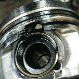
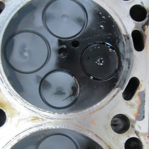
During normal engine operation the injector sprays a very fine mist of fuel. The fuel spontaneously combusts as it is injected into the cylinder. Temperatures present in the flame front are much higher than the melting temperature of an aluminum piston. A barrier layer of residual combustion gasses protects and insulates the piston crown from the high combustion temperatures. As a result, the burning fuel doesn’t normally come into direct contact with the piston.
If the fuel is not sufficiently atomized, (faulty injector) the large fuel droplets do not completely burn with the flame front. The remaining fuel then penetrates the barrier layer of gases and is deposited directly onto the piston crown surfaces. The fuel then burns in direct contact with the piston, creating a very high temperature zone. The high localized temperature heats the crown in this area to a plastic state. The high temperatures also cause the affected portion of the piston to expand much more than the adjacent cooler areas.
The stress created by this can cause the piston to fracture. The fracture creates a passageway that allows high temperature combustion gasses to burn through the crown. This allows engine oil to be drawn into the combustion chamber. The engine oil is then burned as additional un-metered fuel, creating even higher combustion temperatures and additional damage.
Holes eroded through pistons are generally caused by injector nozzles not fully sealing due to deposits of particulate matter in the injector nozzle. This concern can be exacerbated by trucks running high horsepower aftermarket engine tunes especially when only street driving and towing.
DUSTING
Engine dusting have several characteristics to watch for when assessing a concern and affect all moving parts in the engine. The ingress of dirt allows for the piston ring to be worn on the running surfaces and edges, so they can no longer seal the cylinder sufficiently and can therefore no longer prevent oil from passing into the combustion chamber. At the same time, the pressure in the crankcase increases as a result of combustion gases flowing past the cylinder. This excessive pressure can cause increased quantities of oil to escape through radial oil seals, valve stem seals and other sealing points.
Possible causes for abrasive dirt particles which enter the engine through the air intake are as follows:
- Foreign particles enter past missing, defective, deformed or poorly maintained air filters
- Leaking points in the intake system, such as distorted flanges, missing gaskets or defective or porous hoses
- Particles of dirt which are not completely removed during an engine overhaul
- If first oil change is performed too late, abraded particles from when the engine is run in are then spread through the oil circuit to the other moving parts where the cause more damage
Once abrasive particles have been ingested the wear between the cylinder wall and piston rings allows the crosshatch in the cylinder to be worn away. As the two primary purposes of cross hatch is to keep the piston ring stationary (so does not circle to piston during engine operation) and hold oil for lubrication, once worn away will cause decreased engine performance, hard starting, and oil consumption.
HOT SHORT
A loss or lack of proper lubrication is created when the oil film present during operation is inadequate, either in quantity or quality, to support the loads placed upon it. As a result, the shaft and bearing are allowed to come into direct contact with one another. This action generates accelerated wear, heat, wiping and eventually total catastrophic bearing failure.
An oil film is created inside an engine bearing and maintained by shaft rotation. At start-up, the bearing and shaft briefly touch, but as oil is supplied to the bearing clearance space the oil is pulled by the shaft into the minimum-clearance region. Oil pulled between the shaft and bearing forms an oil wedge (oil film). The oil wedge is what supports the shaft during all loading cycles. This type of lubrication process is referred to as hydrodynamic lubrication and is critical for proper bearing operation.
Wiping of a bearing occurs when the crankshaft journal comes into direct contact of the bearing surface because the oil film is penetrated. Once the wiping sequence begins, temperatures become elevated by friction of contact. High temperatures cause considerable softening of the bearing material, which leads to the displacement of the material. Severe wiping of a bearing can best be described as an advanced stage of oil starvation which can progress into a hot short condition.
“Hot-Short” is a metallurgical term used to describe the process of which a bearing material is caused to delaminate in the presence of high temperature and shear stress. Once a lack of lube condition has initiated, regardless of the cause, the resulting friction of the bearing operating temperatures to rise quickly. By 375 degrees Fahrenheit conventional engine oils have lost their lubricity and begin to vaporize. Without lubricating oil, bearing temperatures accelerate quickly. As temperatures surpass 620 degrees Fahrenheit, lead in the ally begins to melt and leach from the alloy intermediate layers microstructure. Under the shear stresses imposed by contact with the rotating shaft, the intermediate layer loses its bond with the steel backing and relatively large areas begin to be torn from the backing material.
If an engine is built with the correct assembly clearances it can still suffer premature failure from running incorrect oil grades for the outside ambient temperature. For example using a 15w40 in -30 Celsius (-22 Fahrenheit) or colder or a 0w30/10w30 in +10 (50 Fahrenheit) or hotter can lead to this concern given the loads placed on the engine. Always reference you DFC owner’s manual or factory owner’s manual for proper grades of oil to be using for you conditions.
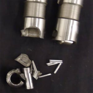
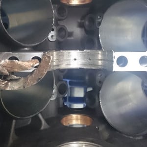
BENT CONNECTING RODS
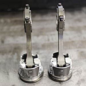
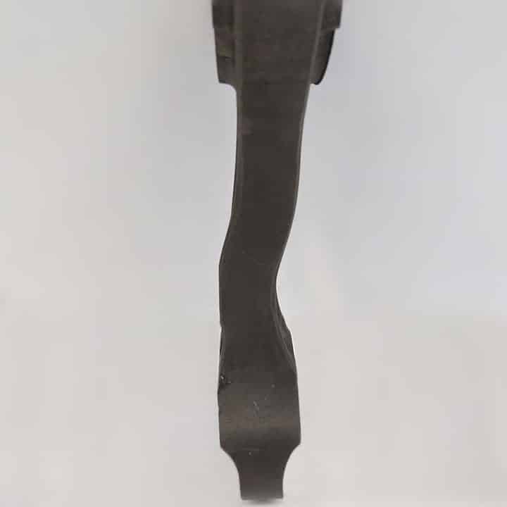
Hydrostatic lock occurs when a volume of liquid greater than the volume of the cylinder minimum (end of the pistons stroke) enters the cylinder. Since most common liquids are incompressible the piston cannot complete its travel; either the engine must stop rotating or a mechanical failure must occur. Diesel engines are more susceptible to hydro lock than gasoline engines. Due to their higher compression ratios, diesel engines have a much smaller final combustion chamber volume, requiring much less liquid to hydro lock. Diesel engines also have higher torque, rotating inertia and stronger starter motors than gasoline engines. The result is that a diesel engine is much more likely to suffer catastrophic damage from ingestion of incompressible fluids.
Typical causes of this concern is from ingestion of fluids through the intercooler, water in fuel and improper torqueing of injector hold down bolts. Always have intercooler and piping professionally cleaned when installing a new engine and follow the original equipment manufacturers recommended torque sequences. If a water in fuel light comes on vehicle should be towed, not driven to a dealer for further inspection.
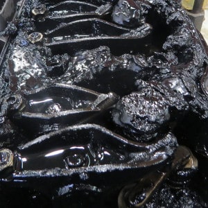
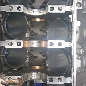
HOLE IN BLOCK (rod bolt failure and bearing failure)
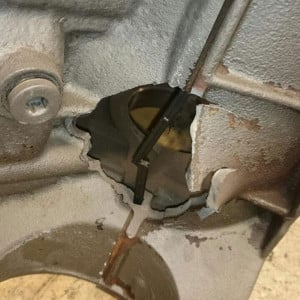
Catastrophic bearing failure can be as a result of both isolated and progressive bearing wear and/or contamination. A progressive failure generally isolates the actual failure towards the end of the engines oil gallery flow, typically rear of the engine assembly.
This can be from both lack of sufficient oil volume and foreign dust, dirt or abrasives and/or metallic particles present in the oil supply. The foreign particles can embed in the soft Babbitt bearing lining displacing metal and creating a high spot as the material is re-plastered to additional bearing materials while the lack of oil volume will cause a wiping of the bearing surface leading to a “Hot-Short” condition. Evidence of either of these conditions will leave some degree of damage and wear throughout all bearing surfaces with “progressive” damage being exhibited as the oil flow travels through the engine creating more debris.
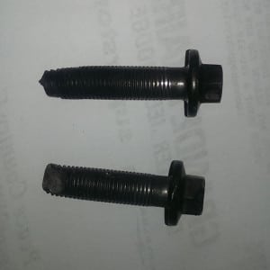
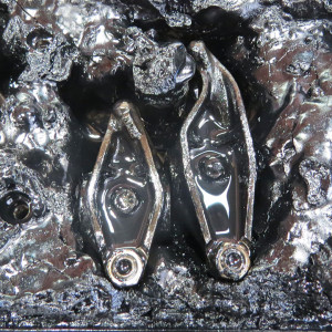
Catastrophic connecting rod failure can be as a result of incorrect clearances causing bearing failure, incorrect torque applied to the fasteners, engine over speeding resulting in hyper-articulation of the connecting rods and connecting rod bolt failure.
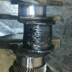
Incorrect clearances will result in seizure of the connecting rod bearing. Once started, through continued operation, the friction, debris and heat generated by the seizure of that bearing can cause the oil to vaporize and create a lack of lubrication condition commonly shared with its partner connecting rod in V8 applications sharing the same rod journal. The generated heat will remove the hardness from the crankshaft, leaving a blackened appearance. With the continued operation this can lead to the connecting rod to disengage from to crankshaft and collide with the rotating assembly. A series of high energy collisions can create a high degree of secondary damage to the engine assembly.
Incorrect torque applied to the fasteners can be observed typically by at least one if not both bolts still intact with collateral damage from a subsequent high energy collision within the engine assembly. As most connecting rod bolts require an engineered amount of “stretch” to maintain torque, once loose can work their way out of their threaded end within seconds. This leaves the bearing lacking any evidence of a lubrication or contaminant concern with the crankshaft journal still polished in appearance with only the subsequent collateral damage caused from the connecting rod disengaging from the crankshaft.
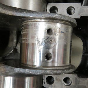
Engine over speeding can be as a result of down shifting an automatic or manual transmission in too low of gear for the current vehicle speed, operating the engine at a higher than designed engine rpm from aftermarket tuning and sudden drivetrain failure on a loaded engine causing unregulated engine rpm gains through inertia. As this failure can happen suddenly it typically leaves the condition of a relatively undamaged bearing and crankshaft journal, excluding collateral damage from the resulting high energy collision, but leaves the threaded end of the connecting rod bolts in the upper connecting rod assembly. This is possible from the bolts achieving their tensile stress point and break at the mating surface where the cap meets the connecting rod.
Connecting rod bolt failure generally leaves the condition of at least one bolt with the head broken off, the bolt split at an angle down its length and the opposing bolt broken off within the upper connecting rod half. This can result in a sudden catastrophic failure resulting in a high energy collision with the connecting rod, crankshaft and block assembly but will leave the crankshaft and bearing assembly with their previous polished appearance with only collateral damage from the collision being observed.
Failure of bearings and rods from contamination and/or oil flow issues are generally as a result of failure to replace an oil cooler from a previous engine failure, inadequate oil amount, missing oil gallery plugs, worn oil pump and blocked oil galleries. Incorrectly torqued fasteners will generally cause failure within the first few thousand kilometres/miles and failure as a result of engine over speeding typically shears both rod bolts off flush the machined or fractured connecting rod joint.
LACK OF MAINTENANCE
Modern diesel engines require the use of a new CJ-4 grade of engine oil. This oil works in conjunction with the new emissions systems such as the EGR (exhaust gas recirculation) DPF (diesel particulate filter) and DEF (diesel exhaust fluid). The goal of these new oils is to help meet emissions by emulsifying excess diesel fuel into tiny droplets within the oil so they can be flushed out at the next service interval. While this practice normally does not cause any excessive bearing or ring wear when proper service intervals are maintained, it can cause a buildup of sludge over time that will lead to premature bearing failure. This sludge buildup normally takes in excess of 20k oil change intervals to start accumulating and can cause catastrophic failure when operated to 50k plus without servicing. This happens through what is defined as a “Hot Short” condition when the lubrication value of the oil cannot support the loads placed upon it and the crankshaft comes into direct contact with the bearings.
This concern is 100% avoidable with proper service intervals.
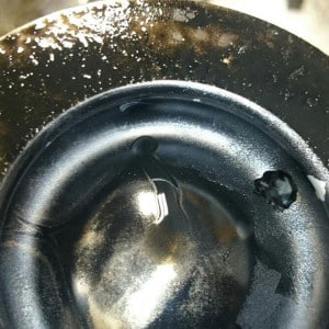
FUEL FLOODING / CYLINDER WASHING
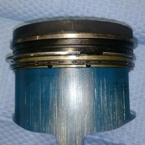
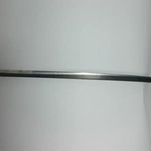
Dry running damage from fuel flooding happens when unburned fuel is wetting the cylinder running surface and has washed off the load bearing oil film. As a result, the piston and cylinder run dry against each other resulting in long, narrow friction marks. This type of damage generally leaves the ring zone undamaged as mainly just the piston rings are in contact with the cylinder running surface. This can be caused most commonly by an over rich operation of the engine, insufficient compression or oil dilution by frequent short distance driving with an overly rich fuel mixture.
Cylinder washing is typically caused from two main causes of either an injection system or lubrication system deficiency. For the injection system the main causes of cylinder washing are connected to an incorrect regulation of the injection pump and nozzles, resulting in a series of changes: quantity of delivered diesel fuel, injection pump rotation, synchronization between governor and pump, synchronization among pump elements, opening pressure and projection of the injector nozzles out of recommendation and the height of the piston crown.
The lubricating oil has a series of functions, two of them are: to participate in the cooling of the internal engine components and to reduce the friction between moving parts. When the combustion occurs at the piston crown, the generated heat is dissipated by the piston rings (mainly by the top ring in first groove). The rings transmit the heat to the cylinder walls and to the existing lubricating oil. The oil film formed between the piston rings and the cylinders reduces considerably the friction, avoiding the direct metal to metal contact. A worn out oil pump will reduce its pumping capacity, having as a consequence, the reduction of pressure in the oil circuit, and jeopardizing the engine lubrication, originating in this way the above mentioned damages.
This concern can be even more prevalent during the initial break-in of the engine leading to oil consumption. It is important to always have your injectors tested or replaced when installing a remanufactured engine and perform regular fuel filter changes to avoid injector failure.
LIFTER FAILURE
Lifter failures have several aspects to consider when assessing damage from the type of lifter (hydraulic or solid) wear or crown surface, lifter bore, clicking or ticking commonly referred to as lash tick, needles within the rollers and finally lifter bounce called “loft” or “launch”.
The majority of lash tick is caused by small particles of debris or dirt that collapse the lifter mechanism. The contamination can cause metal to metal wear causing premature failure which can enter the body of the lifter, giving the needle bearings more room to dislodge from their cage. Hydraulic lifters are also designed from the manufacturer to run up to their service envelope or limit and not beyond getting the most out of the materials used. Lifter tick can also be caused from dilution of the viscosity of the engine oil leading to the lifter unable to stay primed and causing excessive clearance allowing the roller lifter to “launch” off of the lobe peak during high rpm cycling.
Lifter “launch” or “loft” off the cam is when the lifter actually leaves continuous contact with the camshaft. This not only increases the wear on the lifters roller and supporting areas such as the rollers axles and bearings but often establishes a “divot” on the back side of the cam where the lifter comes back into contact with the camshaft. In some cases the lifter will actually skid on the camshaft instead of having a smooth transition of motion.
Another common failure of the hydraulic valve lifter, is rotation that is normally prevented by a series of plastic and/or steel guides. These guides prevent lifter rotation by acting on a pair of vertical flats machined in the top of each lifter. Each guide is typically responsible for a gang of four (4) lifters and is held in place by a single bolt. If a valve lifter is not acted on by this guide it is free to rotate so that the roller then slides sideways along the camshaft lobe trackway creating irregular wear. This irregular wear can result in eventual fracturing of the lifter roller and subsequent camshaft and engine failure.
Proper engine servicing and not operating regularly at high engine RPM’s can help prevent the majority of premature lifter failure.
HEAD GASKET FAILURE
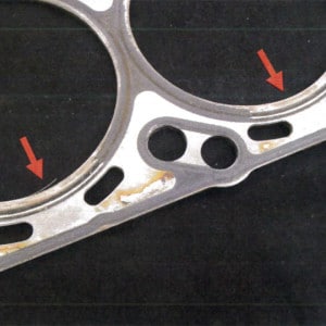
Conventional machining operations cannot provide the very fine OEM surface finish required for a long term seal when utilizing a MLS (multiple layer steel) cylinder head gasket. An overly course surface finish (rougher than 20 RA) produces patterns of peaks and valleys in the mating surface that an MLS gasket cannot conform to. When installed the gasket is supported by the peaks in the surface. The valleys between them then become voids which allow fluid and combustion leakage to initiate which eventually leads to a catastrophic failure of the gasket. An overly course finish also abrades the gasket facing as the castings grow and shrink through cycles of thermal expansion.
Ford 6.0/6.4 head gasket failure additional information
It is indisputable that the Ford Powerstroke engines have a propensity for cylinder head gasket failures. The root causes for many of these failures are unrelated to the sealing joint itself and cannot be detected by an examination of the cylinder head gaskets alone. Cylinder head gasket failures and other engine damage occurring in these engines have found to be directly linked to hydrostatic lock from injector and EGR cooler failures. Another very common root cause for cylinder head gasket failures in this engine are as a result of excessively high cylinder pressures through the utilization of aftermarket performance tuning programs. To produce a viable seal, the gasket relies on an even application of adequate amounts of clamping force. The excessively high cylinder pressures produced by aftermarket performance tuners and hydrostatic lock effectively lift the cylinder head off the cylinder block reducing clamp load applied to the gaskets, breaking the combustion seal and initiates leakage.
DFC can build many of our engines with a stainless steel wire O-ring in the cylinder head or block surface that adds additional contact pressure on the combustion ring of the head gasket(s) and from our experiences can virtually eliminate premature head gasket failures from aftermarket tuning and heavy duty applications.
Common repeat head gasket failures can be as a result of porosity in the block or head casting caused from expanding coolant between the surfaces and are compounded by technicians that use air operated tools to clean surfaces before re-assembly.
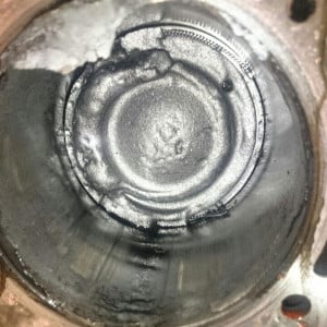
CRACKED PISTON
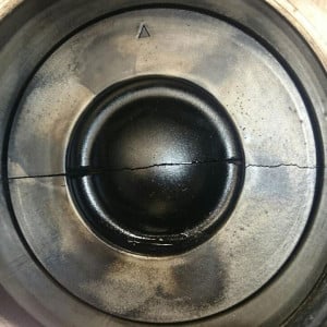
Cracking of the piston crown around the combustion bowl will display radial cracks at the bowl rim on direct injection diesel engines. This is caused from a premature or excessive fuel injection to cause high thermal and mechanical loads causing fatigue as the piston is bent around the wrist pin as it drives the piston through the compression stroke in the presence of excessively high cylinder pressurization and thermal stress. When this occurs the most heated part of the combustion chamber, surrounded by less heated regions, can’t expand in accordance with its expansion coefficient at high temperature. Because the material cannot compress the only way is to expand in the direction of a free surface. A plastic deformation occurs from the accumulated material which once the piston cools, the deformation persists, resulting in tensile stresses which lead to cracks at the combustion chamber corners. The wedge effect in conjunction with the presence of quick changes in temperature fatigues the piston in this area causing the piston to fracture.
Excessive high cylinder pressurization can be the result of malfunctioning fuel injection, advanced fuel injection timing or hydrostatic lock. To reduce the risk of this happening DFC can remove the lip in the combustion bowl helping to prevent radial cracks that can form from extreme thermal tensions.
Excessive high cylinder pressurization can be the result of malfunctioning fuel injection, advanced fuel injection timing or hydrostatic lock.
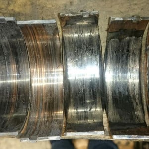
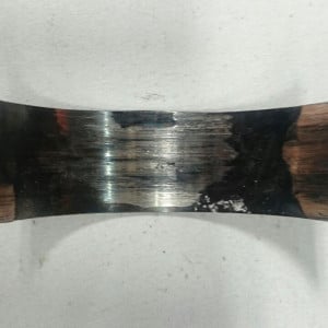
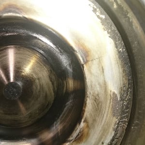
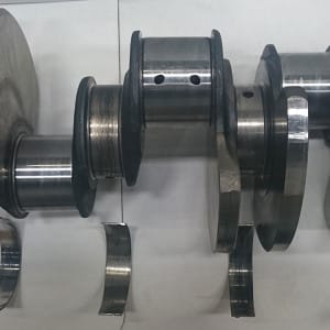
FAILED THRUST BEARING
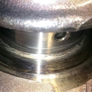
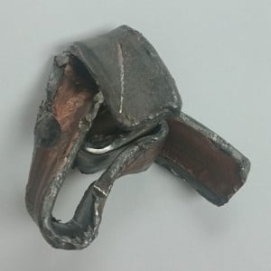
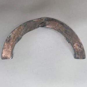
A thrust bearing rear facing (major) thrust side found to exhibit severe thermal discoloration and scoring wear can be attributed to two main causes. These can include a lack of proper lubrication and excessive exterior force being applied to the rear of the crankshaft via the vehicles transmission clutch, torque converter transmission or driveline.
A lack of proper lubrication simply means that the oil film present at some point was not adequate to support the loads placed upon it. This is a result of either a lack of oil film quality or quantity. In general, a lack of oil film quality can result in the degradation of the lubricating oil due to either contamination or dilution, abnormally course mating surface finish, improper clearance, geometric misalignment or the bearing surface in relation to the crankshaft or a physical mechanical overload. A lack of quantity can be the result of inadequate pre-lube during assembly or inadequate volumes of supply oil during operation. A lack of quality or quantity of oil can generally be ruled out as a cause for rear (major) thrust side failure if the remainder of the bearings in the engine show no signs of a quality or quantity of oil starvation.
The most common case of a rear (major) thrust side failure is an excessive exterior force being applied to the rear of the crankshaft via the vehicles transmission clutch, torque converter transmission or driveline. This force can be the result of improper torque converter or clutch input shaft engagement or clearance, but can also be the result of chassis/or driveline geometry and/or damage.
These types of failures will most commonly happen within 5,000km (3,000mi) of an engine or transmission installation but can also frequently happen from a slipping torque converter causing excessive swelling and heat.
These types of failures will most commonly happen within 5,000km (3,000mi) when directly caused by an engine or transmission installation concern whereas if failed after a period of time 50,000km (30,000mi) plus, is more likely as a result of a slipping torque converter clutch causing swelling of the torque converter. In Dodge, Ford and Chevy diesel applications it is not typical to see a worn out thrust bearing solely from clutch pedal application.
OIL CONSUMPTION
Opinions on what constitutes excessive oil consumption can differ widely in practice and from one manufacturer to another. Every engine manufacturer has guideline values and limits they follow for the oil consumption of each of their engines. A general guideline for most engine manufacturers of each engine is 0.25% to 0.5% of the actual fuel consumption.
For example a truck that uses 40 litres of fuel in 100km is 400 liters in 1000km. 0.25% of 400 litres equals 1 litre of oil. At 0.5% of 400 litres equals 2 litres of oil. While these limits seem extreme the actual oil consumption of the engine will be determined by a number of factors, most commonly ranging from low quality mineral oils, leaking radial oil seals and valve guides, running in phase, cylinder distortion and machining faults during honing.
Low quality mineral oils can cause oil consumption through accelerated wear during cold starts and overly high temperatures. The proper grade and viscosity should always be followed according to the manufacturer’s specifications for the outside ambient temperatures and operating conditions.
Leaking radial oil seals such as stem seals around intake and exhaust valves and valve guides can allow oil to enter to the intake and exhaust tract where they can be either burned or discarded.
The running in phase of an engine can put any bearings and shafts with tight clearance tolerances at particular risk. Together with the cylinder liner, components which undergo translational movements (i.e. parallel movements back and forth) such as pistons and piston rings are among the most sensitive engine components. As modern materials are becoming increasingly resistant to wear, component pairings take a certain amount of time to adapt to each other. As a traditional “rule of thumb” a new engine should be treated with care for at least the first 1,000km (600mi). During this time the engine should avoid being idled or operated at low rpms and should not be operated at full engine power until at full operating temperature. The complete running in phase of an engine should be over by 10,000km (6,000mi).
Due to their operating principle, diesel engines consume more engine oil than gasoline engines. It is however clear that oil consumption is at its lowest after its running in phase and increases over the service life of the engine. The minimum values should therefore be viewed as being applicable for new engines and the maximum values for engines that have already completed 2/3 of their service life. When assessing an engine for oil consumption all these items much be inspected as their application is relevant;
- Excessive bearing clearance in turbocharger
- A blocked oil return line in the turbocharger
- A worn fuel injection pump
- Oil escaping into the air intake system
- Worn valve stem seals and valve guides
- Errors during installation of the cylinder head
- Excess pressure in the crankcase
- Excessively high oil levels
- Combustion faults and fuel flooding
- Incorrect piston protrusion
- Irregular maintenance
- The use of low quality mineral oils
- Cylinder distortion
- Graphite exposure rate being too low
- Twisted/distorted connecting rods
- Broken, jammed and incorrectly installed piston rings
- Incorrect, excessive or forgotten sealant
- Overlooked foreign bodies on sealing surfaces
- Leaking radial oil seals
- Surface faults at mating surfaces
- Defective vacuum pumps
- Excessively high oil pressure
Oil consumption issues of a newly remanufactured engine when cylinder distortion and cylinder finish are not a factor are typically from incorrect break-in procedures, over fueling injectors and poorly maintained/installed air filter system.
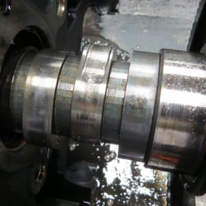
DISTORTED CRANK/MAINLINE
A distorted crankcase gives the appearance in the bearings of accelerated wear on both the upper and lower shells, usually originating in the center main working outwards. The degree of wear from bearing to bearing varies depending on the nature of the distortion. The point of the greatest load on the bearings causes the greatest distortion (center main). With too much distortion extreme bearing wear can be experienced which can lead to reduced oil clearance. This reduced clearance can lead to metal to metal contact resulting in further failures such as a “Hot Short” condition.
Any engine built with a distorted crankcase mainline or bent crankshaft will fail in a short period of time usually less than 2,000km (1,200mi). Any engine that develops a distorted crankcase mainline during its service life is generally due to an overheating concern.
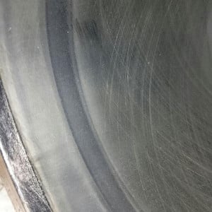
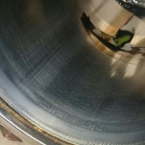
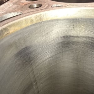
POLISHED AREAS IN UPPER PART OF CYLINDER
Polished areas in upper part of cylinder damage occurs when a hard oil carbon deposit forms in operation on the piston top land as a result of burned oil and combustion residues. This coating has abrasive properties which lead to increased wear in the upper part of the cylinder in operation due to the reciprocal motion and the change of bearing surfaces on the piston. The increased oil consumption is not caused by the polished areas themselves, as the polished areas do not cause a noticeable out-of-roundness of the cylinder, and the piston rings can still continue to perform their sealing duties in a normal fashion. The lubrication of the cylinder is also unaffected, as it is still possible to retain enough oil in the open graphite veins to the cylinder surface despite the loss of the honing structure.
It is important to note that, in this case, the polished areas all coincide with points in the cylinder which come into contact with the carbonized piston top land. If the polished areas are also present at points which do not come into contact with the piston top land, then the cause for damage is more likely to be found in distortion of the cylinder from uneven wear due wear on pistons, piston rings and cylinders caused from fuel flooding or wear on pistons, piston rings and cylinders caused from the ingress of dirt.
Installation of cylinder head studs in some applications can lead to cylinder distortion that exacerbates this situation. Improper break-in procedures and over fueling injectors further compound this problem. If a remanufacturer uses an incorrect cylinder finish and does not plateau finish this concern can also be experienced.
INJECTOR TESTING
Currently most late model Dodge, Ford and Chevy diesel engines utilize a high pressure common rail fuel injection system from either Bosch or Siemens. These injection systems have increasing tight tolerances and design parameters to meet both emissions and the power requirements from the manufacturers. Depending on the ECM/ECU utilized by the OEM the same injection system can have different power output depending on what is commanded of it. All current test stands operated by authorized dealers for these injector manufacturers come with their own operating system that are designed to test key sections of the injector cycle but do not actually run a complete cycle as the injector would operate in the truck. This is to say that the parameters checked on the injector during testing are only to verify that at that moment the injector is able to fall within a certain range at that instant, but once re-installed in the vehicle could give a completely different outcome. The ultimate operation of the injector is governed by the ECM/ECU in the vehicle, aftermarket tuning alterations and the fuel quality and quantity being supplied to the injection system.
DFC recommends replacing injectors rather than testing due to the varying and incomplete results that injector testing sometimes provides. Your new remanufactured engine is an investment and can be jeopardized with malfunctioning injectors.